Heathkit Gr 1290 Manual Transmission
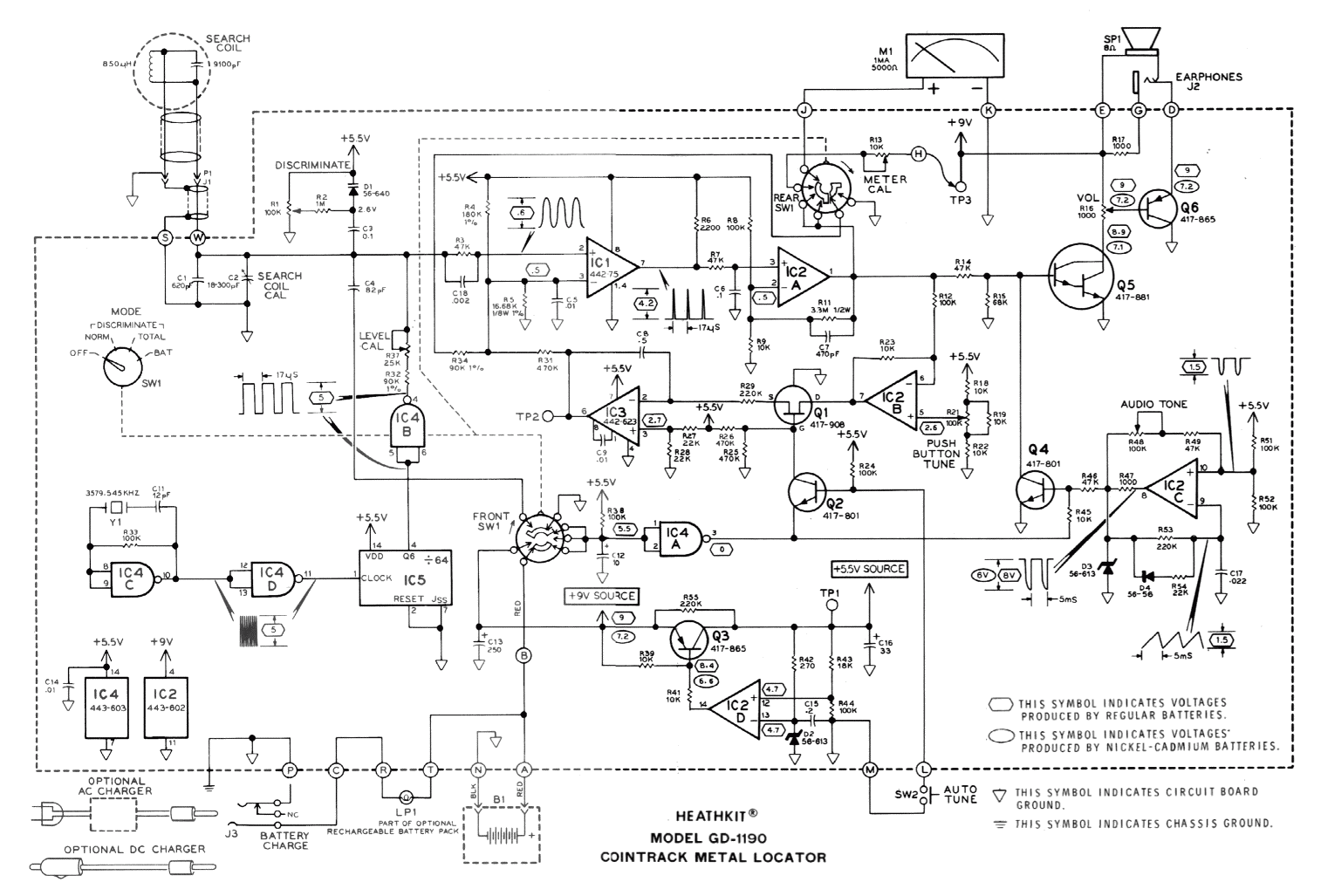
Hi, I found this Heathkit VLF metal detector and became intrested in it. I think i have worked out how most of it works, there are a few bits i am not sure about and was hoping someone could explain them to me. This is for a VLF Metal detector which from what i have read looks for small phase changes to determine if metal is found. I may have this all wrong as i am new to electronics but i think that Q8 L1 & L2 are acting as some type of oscillator transmitting a 7.3Khz signal.
How to Rebuild a Muncie Four-Speed Transmission Rock The Rock Crusher Giving a worn-out Muncie four-speed transmission a quick rebuild with parts from Summit Racing. Crusher TV 85 diagram Newest Crusher, Grinding Mill, Mobile. Printed circuit board heathkit gr 1290 Crusher South Africa. Heathkit Circuit Board. Powerfix Plw2 Manual Transmission. Hi, a 6ya expert can help you resolve that issue over the phone in a minute or two. Best thing about this new service is that you are never placed on hold and get to talk to real repairmen in the US. The service is completely free and covers almost anything you can think of.(from cars to computers, handyman,.

L3, Q1 & Q2 the signal is received by L3 and amplified by Q1 & Q2. Q9 & Q10 allow you to manually adjust the phase to correct for changes to the ground conditions etc. (this is because there may be a constant phase difference due to minerals in the ground, this can be effectively nulled out using Q9, Q10 does a similar task but to null out the types of metal you don't want ie ferrous) the output form Q9 and Q10 is fed into U4C which i think is working as a schmitt trigger to produce a square wave.
This is then used to switch Q3. As Q3 switches some of the signal from Q1/Q2 will be allowed through, the amount of signal that come through will depend of if it is in phase or not. I think C8 is being used to smooth this signal so that the result is a varying voltage related to the phase. This is then fed into U2, I am not sure if U2 is an integrator or a single pole filter, i think its a filter as this would make more sense. The output of U2 controls the audio Q6 & Q7 what i am really not sure about is U4A, Q5 and U1, to me it looks like U4A is a pulse generator which is switching Q5, U1 turns this into a triangle wave which is fed back into Q3 but i don't know why?
The other odd thing is U4D which i think is being used to stop something only when the switch is used maybe stop the speaker from popping or something like that. Thanks to everyone who helps me with this.